 |
||||
|
||||
1 |
(1) From left to right: Aero Detail #31 published by Dainippon Kaiga Co, Mechanic of World Aircraft #7 (also known as one of the “Maru Mechanic” series), "Flying Boats" published by Gakken, and "Imperial Japanese Navy Flying Boat" by Nohara Shigeru. |
|||
|
(2) I began by enlarging the wonderful Aero Detail #31 drawings to 1/48. My airfoil cross sections I produced and used are laying on top of the drawing. |
 2 2 |
|||
|
There are two sets of different drawings 'out there' for the Emily. Both the Aero Detail #31 and the Mechanic of Aircraft #7 books have drawings. From my calculations, and referencing available photographs, the Aero Detail’s drawings looked the more accurate. However, I must admit that both drawings had issues. In the end, I used them both, and constantly referenced the real aircraft photos. Fortunately, one Emily was saved after the war for evaluation. After traveling to Norfolk, Virginia, USA and following years of storage, the aircraft was returned to the Japanese and was restored in the 1980’s. The surviving aircraft is located in Tokyo and is nothing short of amazing. It was this aircraft that the above books featured photos of and that I used so closely for reference. (Click here for walk-round images that show just how good Stefan's model is - SEAWINGS) |
||||
3 |
(3) Using artist's clay I fashioned the left side of the fuselage following the bulkhead outlines that I had made from the drawings. Then, the bulkheads were cut out of styrene plastic and glued to the side profile shape of the aircraft and then clay was then used to fill in between the bulkheads. The hardened clay was then placed on my chop- saw and cut 50 times correlating with the fifty bulkheads on the real aircraft. |
|||
4 |
 5 5 |
|||
|
(4) Once the bulkheads were cut, they could be duplicated for the right side of the fuselage by tracing their outline onto paper. The outlines were then copied using the mirror image function on a copy machine. The bulkhead outlines were then traced onto sheet styrene and cut out. (5) The wings were created by taking precise measurements from the drawings and programming that data into a wing lofting program. I used the excellent Compufoil program that can be found online. This program is used by RC model builders and is a simplified CAD program for wing design. I spoke with the Program Designer several times, and he was extremely helpful. I would strongly recommend Compufoil for anyone with scratch building interests. Note: the Emily had a slight 4 degree downward wing dihedral which occurred about mid way down the wing. This is reflected in the main wing spar (the long square piece lying between the ribs). Compufoil was able to take that negative 4 degree dihedral into account. |
||||
6 |
 7 7 |
|||
|
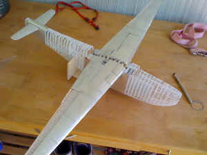
(6/7) The completed skeletal airframe is seen in these two pictures. In an effort to capture the look of the real aircraft, I decided to build it in the same fashion as the real aircraft was built, using a multitude of ribs and stringers. In viewing photos of the real aircraft, there is a bit of skin sag, and I felt that it would be very realistic if you could see just a little bit of the skeleton under the skin. A first layer of .003thou aluminum shim stock can be seen here. A second layer was glued on later which would reflect the correct panel lines and become the final surface to be painted. The 'transparent' portions that show on the model wings are areas covered in good old fashioned tissue and dope to simulate the fabric covered areas of the aircraft. The canopy was vacuformed and checked for fit. |
||||
8 |
 9 9 |
|||
|
(8/9) The engine nacelles were vacuformed. Note the final skin application of aluminum .003 thou shim stock has been applied in these views. Nearly all of the skin on the actual H8K was overlapped, just like the B-17, so doing it like the real aircraft would yield the best results although it was very time consuming indeed! The fuselage was built with locating pins so it could be split in half in order to build the interior. |
||||
10 |
 11 11 |
|||
|
(10) Extensive flight deck detail work was done. A bit of patience was required here to ensure that everything fitted as well as it could. (11) Here the nose section detailing is completed including the oxygen bottles. I was not sure how much would be visible from the outside after it was all closed up and the cockpit canopy was finished. Sadly, a lot of detail could not be seen from the outside but at least you can see it here, and I know it's all in there somewhere!. |
||||
12 |
(12) The rear portion of the aircraft was primed in a light silver-grey color in contrast to the cockpit which was approximately Mitsubishi Interior Green. Some of this detail would be visible once the hull halves were joined as I was planning on leaving off the side blister transparencies themselves. Also for the same reason the rear doorway, just visible on the upper hull at the extreme left of this image, was going to be left open. |
|||
13 |
||||
|
(13) The flaps and ailerons are seen here. Note the tissue and dope covering the ailerons, just as the real ones were. Each of the assemblies are strong, yet delicate, at this stage. Once finished with their respective surface coverings they were not affixed to the airframe until the final assembly after main painting had been completed due to them being liable to damage as I moved the model around. |
||||
14 |
||||
|
(14) The Emily is primed and ready for painting. Note the control surfaces and engine cowls laid out as separate assemblies. The undercoat served to show up any imperfections in the surface, which were then filled and smoothed ready for the final camouflage colours to be applied. |
||||
15 |
 |
|||
|
(15/16)The particular markings that I chose for my aircraft were taken from a photo of one at a Japanese seaplane base. The H8K had a very interesting flap design that was also found on the earlier H6K Mavis. The flap was a fowler flap, but it then had a split flap on the flap itself. You can see this on the trailing edge of the flap. The notch in the split flap is there for carrying torpedoes. However, the Emily rarely used this feature in action. |
||||
17 |
 18 18 |
|||
|
(17/18) The aircraft in the photo had extensive peeling of its green paint on all fabric surfaces. The fabric was primed with a silver primer and that is what is showing through. An interesting note is the amount of fabric that was used on the aircraft aside from the usual control surfaces. Large aft portions of the outer wing were covered in fabric to save weight. |
||||
19 |
 20 20 |
|||
|
(19) Like the Shorts Sunderland, the Emily had fold out workstations that extended from the leading edge to facilitate ease of maintenance in the field. You can only imagine working from one of those stations while the aircraft was in the water. Don’t drop your wrench! The engines were the only thing in the entire project that was not scratch built. They are the incredible Vector engines. They are expensive, but they are absolute masterpieces. Whoever built the mold on those is a real artist. (20) Sadly, a lot of detail can not be seen. However, I would rather over-detail, than under-detail and regret it later once everything is closed up. |
||||
21 |
 22 22 |
|||
|
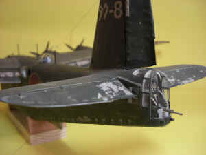
(22) This view shows the extensive weathering on the wings and flap areas which is determined by the type of surface such as metal or fabric, of course. (22) I decided to leave the rear teardrop transparencies off as well as the machine gun mounts so the viewer could see the interior better. The rear teardrop was removable and was often seen open like this. Most of my reference photos show the guns left off. They were probably installed prior to a mission. |
||||
23 |
 24 24 |
|||
|
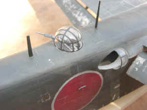
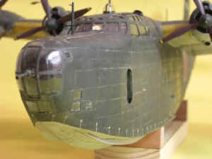
(23) The tail gun turret, like the aircraft, was large. It provided a rotating turret seat that held a type 99 20mm gun. The rear windows opened in a clamshell-like fashion. (24) The impressive nose profile showing the front turret. |
||||
25 |
 26 26 |
|||
|
(25) The very advanced the H8K2 hull design is quite visible in this underside photo. When evaluated by the US Navy after the war, it was noted that the hull design was far superior to US designs. (26) This close-up of the nose shows the turret to good advantage as well as the open forward entrance door that serves to show some at least of the interior details. |
||||
27 |
 28 28 |
|||
|
(27/28) These overhead views show the extreme size of the Emily when placed next to an A6M3 Zero fighter. The tail of the Emily is nearly the size of the Zeke’s wing, yet the scales are the same! |
||||
29 |
 30 30 |
|||
| (29) A close-up of the port under-side flap area showing the dropped flaps and float with its associated rigging details. (30) The corresponding upper surface view showing the dropped flaps. The model is resting on a purpose-built stand. | ||||
| Model Gallery - Additional Pictures | ||||
 |
 |
|||
 |
 |
|||
 |
 |
|||
 |
 |
|||
 |
||||
