 |
|||||||||||||
 |
|||||||||||||
|
Article reproduced by kind permission of Author: Andy McCabe and Scale Aviation Modeller Editor: Gary Hatcher |
|||||||||||||
| g | |||||||||||||
|
|
The Kit | ||||||||||||
| g | |||||||||||||
|
The Short S.25 Sunderland was a long range patrol bomber designed and built by Short Brothers for the Royal Air Force (RAF) just before the outbreak of the Second World War. It’s first flight was on the 16th October 1937 and entered service in 1938. 777 were built between 1938 and 1946 and the aircraft saw service not only with the RAF but also with the Royal Australian Air Force, Royal New Zealand Air Force, Royal Canadian Air Force, Norwegian Air Force, Portuguese Navy, South African Air Force and the French Navy.
The Sunderland was powered by 4 × Bristol Pegasus XVIII nine-cylinder radial engines giving it a range of 1,780 miles, the Aircraft had a crew of between 9 and 11 consisting of two pilots, a Navigator, Radio Operator, flight Engineer, Bomb Aimer and 3-5 gunners depending on the configuration. The Sunderland could carry up to 2,000lb of bombs that were hung underneath the wings and traversed out on rails from inside the fuselage. It was was eventually retired from service by the RAF in 1959.
The Italeri kit consists of 5 sprues of grey and one sprue of clear injection moulded plastic, one etched brass fret, one instruction assembly booklet, one fact booklet and one decal sheet. The plastic parts have heavily engraved panel lines and surface detail, the etched fret is nicely produced if not slightly a bit too thick, the decals are nicely printed with excellent colour registration and density.
The instruction booklet has colour call outs in either FS, Model Master or Italeri paints at the various steps during the build and the little fact booklet also supplied has some very nice photo’s and drawing that are useful for reference. |
|||||||||||||
| g | |||||||||||||
|
|
Construction | ||||||||||||
| g | |||||||||||||
|
The build commences by assembling the interior which consists of the forward section containing the anchor/winch bay, cockpit, navigator position and radio operators position, then there is a gap and then the bomb bay and then nothing after that.
I initially assembled these as per the kit instructions but the huge gaps between the sections did not look right so I set about researching what was missing, this turned out to be quite a lot so I decided to fill in the blanks, I did not realise at the time how much work would be involved.
The only way to describe what was done is section by section starting at the nose/bow and working aft. |
|||||||||||||
| g | |||||||||||||
|
|
Anchor/Winch Compartment | ||||||||||||
| g | |||||||||||||
|
The majority of this area was built straight from the box with no modification, the floor being nicely perforated as per the real thing. The anchor was not put on the floor as the instructions show, this would be glued into position on the Starboard side wall later on.
|
|||||||||||||
|
|
Cockpit | ||||||||||||
| g | |||||||||||||
|
The cockpit was built straight from the box, the pilot and co-pilot seats have etched seat belts and rear supports, the etched fret is quite thick and the belts will not bend easily neither will the seat backs, it is probably wise to anneal the brass fret to allow the parts to bend easier.
The instrument panel can either be made from a panel with raised instrument dials or by removing the raised detailing and using a decal with the instruments on and an etched panel, I chose the latter as I much prefer this method.
|
|||||||||||||
| g | |||||||||||||
|
|
Navigators Station | ||||||||||||
| g | |||||||||||||
|
The Navigators station in the kit is not as it was on the information I have on the Mk.1, there are instruments above the desk and the desk is too small, the desk was cut away, leaving the seat in position, and a new desk was scratch built and fitted into position.
|
|||||||||||||
|
|
Radio Operators Position | ||||||||||||
|
This was the first major rebuild. The bulkhead that is in-front of this position is not correct as it does not span the entire floor on the real aircraft, so it was cut down level with the radio operators desk position.
The radio position had no desk or seat and the radio equipment although nicely depicted was not deep enough, the radio equipment fascias were carefully cut away from the bulkhead with a sharp scalpel and then fitted to thick styrene sheet to give them depth, a small end plate was also made for the inner edge of the desk and radio equipment.
Aft of the Navigator and radio operators position there should have been a bulkhead that is also the forward main wing spar, this was missing so one was made, this extended down to the lower floor. |
|||||||||||||
| g | |||||||||||||
|
|
Lower Level Forward | ||||||||||||
|
The floor from the cockpit steps aft is stepped downward by approx. 6mm, this is not the case on the kit parts, so the floor from the base of the steps was cut away and strips of 6mm wide plastic were added, a new floor was then made, this new floor level then runs completely aft until just after the bomb bay.
Either side of the forward part of the cockpit stairs were bulkheads with doors, on the starboard side the door led to a toilet compartment, here the bulkhead and door were made but no detailing to the toilet compartment was done, on the port side the bulkhead was made and fitted along with another bulkhead aft of the crew access door.
Aft of this was one of the crew rest rooms, this was entirely scratch built and included all of the ribbing to the bulkhead and door, table and bunks/seats, this filled in one of the voids missing from the kit, aft of this was the galley. |
|||||||||||||
| g | |||||||||||||
|
|
Galley Area | ||||||||||||
| g | |||||||||||||
|
Another entirely scratch built section was the galley, this entailed detailing the bulkheads and making the galley units, sink, stove and Ice Box and doors.
When painted I was quite impressed with the result, this area also had the ladder that gave access to the Flight Engineers station on the floor above, the ladder was scratch built using strip styrene from the Plastruct range, most of the detailing added to the bulkheads and doors were from this range as it saved cutting a myriad of different widths from sheet. |
|||||||||||||
| g | |||||||||||||
|
|
Flight Engineers Station | ||||||||||||
| g | |||||||||||||
|
This is another completely scratch built section as is the equipment bay opposite it, this was made using references from photo’s and drawings and is as accurate as I could get it, the flight engineers desk, chair, instrument panels and engine controls were all made from plastic strip and sheet.
The equipment bay opposite on the port side was again completely scratch built, only the basic detail was added as I could not find decent reference photos of exactly what was fitted here, the floor to this section had an access hole from the Galley below via steps mentioned previously. |
|||||||||||||
| g | |||||||||||||
|
|
Depth Charge Bay | ||||||||||||
| g | |||||||||||||
|
This required modifying by adding 6mm strips as per the forward section, this compartment also doubled as a crew rest room so bunks and a table were scratch built.
The aft bulkhead to this compartment was also incorrect as the upper part of the lower section of it had a curtain that was dropped down when the bombs were being loaded etc, I removed the kits bulkhead and scratch built an entirely new one along with it’s door and strengthening ribs. |
|||||||||||||
| g | |||||||||||||
|
|
Aft Hull | ||||||||||||
| g | |||||||||||||
|
Immediately aft of the bomb bay bulkhead was another crew rest area that
contained two bunks, these and the floor were scratch built, the floor
aft of the bunks stepped upwards and carried on to a point just aft of
the rear crew access door where it was replaced by a slatted floor, all
of this was scratch built. Above the crew bunks in this area are the waist gun positions, the floor to these positions is part of the bomb bay roof supplied with the kit parts, however it is a solid part throughout, the walkway above the bunks was not a complete floor, it was open on both sides, there was only a walkway to an access door above the bomb bay into the flight engineers compartment, the two panels were removed above the bunks leaving only the walkway remaining. The waist gun positions were upgraded using strip plastic to create the framework around them, the walkway guide ropes were also added using very thin plastic rod.
Above the bomb bay/crew rest area there were two racks for flares etc, these were fabricated from strip styrene and glued into position, the forward bomb bay bulkhead was extended up to the fuselage and a door added, this was also the rear wing spar and styrene rod was added to represent this.
I also made the ladder that was used for engine maintenance that was stored along the walkway above the crew rest area and the small ladder up to the port waist gun from the aft fuselage floor. The step up to the port gun position were also made and fixed into position. At this point the bulk of the interior was complete, it just needed painting now. |
|||||||||||||
| g | |||||||||||||
|
|
Detail Painting, Fitting Out and Final Assembly | ||||||||||||
| g | |||||||||||||
|
The majority of the interior surfaces on the Sunderland were left in bare Aluminium or painted with Aluminium, apart from the forward and rear most sections of the fuselage which were interior green and the cockpit which was Matt Black.
As most of the forward section had already been painted and detailed it was masked off and the remaining areas sprayed with Tamiya XF-16 Aluminium, the bunks and tables were then painted with what I guessed were the correct colours for the time.
The entire interior was then dry fitted into one of the fuselage halves just to make sure that it fitted as it should, which it did thankfully. This assembly was then put somewhere safe and the fuselage halves were next.
The panel lines are very deep on all of the parts, I did not think that multiple layers of paint would lessen their depth so I decided to make life even more difficult and fill them all, this was a laborious messy task that took a long time and a lot of plastic filler to complete.
I could now return to the kit properly and begin the assembly, the bomb bay underwing doors were painted and the glazing installed and they were then glued into the open position inside each of the fuselage halves. The interior was then glued into the starboard fuselage half along with the anchor. The crew access doors on both sides were now glued in the open positions inside the fuselage, there are clear parts supplied for the cabin windows, I did not use them as I would fill the holes with Micro Krystal Klear later on.
It was now time to hide the interior and all of the work that entailed forever by gluing the fuselage halves together, but not before a multitude of photographs were taken from every conceivable angle just to remind myself that I had actually done it. The cockpit glazing was now masked and glued into position, although the fit is quite neat I still needed a bit of filler to blend it into the fuselage.
I now fitted the tail fin half to the one on the stbd fuselage half and then assembled the wings and tail planes. The bomb racks for underneath each wing were now assembled, these consist of both plastic and etched parts and slide onto rails mounted in each wing, the bombs would be added at the end. Fitting each wing was done in two sittings to allow the cement on each one to dry thoroughly before fitting the other one, the same applied to the tail planes.
The nose and tail gun turrets were now painted, assembled, masked and fitted to the fuselage. Next up were the engines, these are quite nicely detailed and respond well to a dark wash and dry brushing when painted, each engine is fitted into its respective cowl before it is fitted to the wing, three engines are the same whilst the fourth, the port inboard engine is slightly different, the difference is in the exhausts, the three have the exhaust at the top of the engine whilst the port inner has the exhaust going into the wing leading edge and then exhausting through the wing top.
The outrigger sponsons were next, holes require opening up to accept the rigging, the outriggers were assembled and then glued to each wing, holes were drilled into the wing undersides to accept the rigging, the rigging was fitted using plastic rod, I felt that this needed doing sooner rather than later as the outrigger struts are very thin and would break off very easily, adding the rigging strengthened them up markedly. The two waist gun cowlings were now fitted into position, there have etched frames that are fitted into each one of these.
The model was now ready for a coat of primer. |
|||||||||||||
| g | |||||||||||||
|
|
Painting and Decals | ||||||||||||
| g | |||||||||||||
|
A coat of grey acrylic primer was sprayed all over, any gaps or blemishes were filled and then another coat of primer was applied.
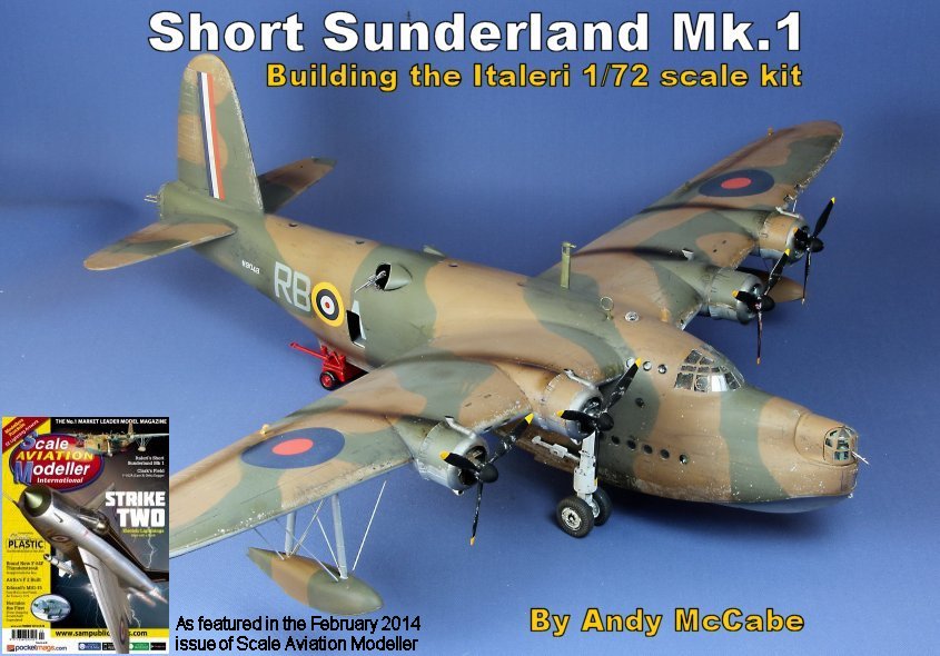
Although there are six colour schemes that can be modelled in the kit I decided that I wanted to apply a colour scheme of the Sunderland based at RAF Mountbatten at the beginning of the Second World War. At the beginning of the war Short Sunderlands carried the Temperate Land Scheme of Dark Earth/Dark Green with Aluminium painted undersurfaces as the Temperate Sea Scheme paint was not yet available, as the Temperate Land Scheme paint was designed for land planes it did not last long on Sea Planes in the harsh environment in which they operated it soon flaked or wore away, Sunderlands were then re-painted with the Temperate Sea Scheme as and when possible, possibly during maintenance or re-fitting periods.
RAF Mountbatten was the home of No.461 and No.10 Squadron Royal Australian Air Force Short Sunderlands and this model is painted as one of No.10 Squadron RAAF from that period in the Dark Earth/Dark Green/Aluminium scheme. There are references that suggest the undersides were painted in grey or sky but I could find no confirmation as to the correct colour for my chosen subject, although I strongly suspect that the Aluminium finish is the correct one.
The model was now given an all over coat of Tamiya XF-16 Flat Aluminium, the reason is that I wanted to remove some of the camouflage later on to represent the wear on the painted surfaces. The under surfaces were then masked and an all over coat of Gunze H072 Dark Earth was sprayed on, when dry this was masked using a combination of Blu Tak and masking tape and Gunze H073 Dark Green was sprayed on. When dry the masking was removed, this also removed patches of the camouflage scheme to reveal the Aluminium below, normally this would have been a disaster but on this occasion it was perfect!
After allowing the paint to dry for a further 24 hours a removed more paint by masking tape or chipping away with a scalpel, I then also lightly sanded the surfaces to wear away the crisp edges to the camouflage scheme.
The next stage was to apply the decals, these would be a combination of the kit decals and registration codes from the Kits World range, both kits World and Xtradecal supply bespoke decals for Mk.1 Sunderlands of this period and I did contemplate purchasing a set of the Kits World Decals sets but I already had the serial codes from them and the kits decals are pretty good which would have meant that I would have spare Sunderland decals from the Kits World set that would in all likelihood never be used.
The decals were applied and then a coat of dark wash was applied, not that there were that many panel lines left for it to settle into that is.
A coat of Revell Matt Varnish was then applied and the masking removed, Tamiya smoke was sprayed on to the upper wing surfaces from the exhausts to represent exhaust stains, it was also sprayed along the waterline and other areas that were know to get really grubby.
The beaching gear was now assembled and painted and then fixed into position. The props were now painted and then fitted to the engines along with their spinners, the bombs were assembled and painted Dark Green with a red band around the nose, then fitted to the racks, finally the aerials were fitted on top of the fuselage and a rather long project finally came to an end. |
|||||||||||||
| g | |||||||||||||


