|
I
have a passion for the difficult and unusual: a little like me,
really! So it will come as no surprise that I model classic
airliners in 1/72nd scale. When I started out there were
very few on offer; airliner modelers worked in 1/144th.
One of my earliest successes was converting an Airfix
Sunderland into a Sandringham. I filled in the round windows,
turrets and bomb racks with Milliput, and cut new square windows. I
shaped and sanded the model, sprayed it silver and was hooked.
Hellers Connies and DC-6s followed, as did numerous Daks but
what I really wanted was Imperial Airways and BOAC in their heyday.
This meant vac-forms! I
didnt think I was good enough for the challenge but after much
procrastination bought a Carvair to join my Bristol Superfreighter.
I was careful to follow instructions and ended up very pleased with
the result.
Vac-forms
and resin products have proliferated over the years and I now have a
collection of some wonderful models. Then I discovered Combat Models
from the USA and their big boats! I have still to make the
Dornier Do-X (Hilton Jones model of this is fantastic!) but I did
make the Boeing 314 Clipper (written up for SAM in 2002). Then at a
model show some years ago I came across an old Contrail model of the
6-engined Latecoere 631. I bought it, cut out the main components
and then shelved it. It looked huge and somewhat daunting. My modeling
progressed and I made the excellent Aerovac (a French
company) vac-form of the Latecoere 521, the 631s predecessor.
Finally feeling confident and interested enough, I dug it out to try
again.
Then
I made a fateful decision: I wanted this to be the best and most
detailed model I had ever made. On the Late 521 I cut out and
lowered the flaps, ailerons and elevators, and off-set the rudder.
It made a huge difference. I would do the same on this model and
super-detail it! I have also decided to write up and
photograph my progress rather than report on the finished product.
We shall see how I get on.
History
In
1936 the French Air Ministry issued a specification for a large
transport flying-boat capable of carrying 40 passengers over 6,000 kilometers
against a 60kmh headwind. Three firms designed planes to
meet this specification but only the Latecoere 631 eventually made it
into production. Construction started in March 1939 in Toulouse but
was interrupted by the outbreak of war.
There
followed the most extraordinary story..............
After
the armistice, construction resumed under the Vichy government. As
Biscarosse was in the occupied zone the decision was made to assemble
and test the prototype (and the other two prototypes: the LeO H-49 and
the Potez-Cams 161) at the Etang de Berre. All three planes were moved
by road convoy from Toulouse, where they were built, to Marseilles
where they were assembled and readied for testing. The Late 631 was
given the registration F-BAHG and was painted grey with orange nose
and wings.
The
testing, despite onerous conditions imposed by the Germans, was
successful but in January 1941 the Late 631 was confiscated by the
Luftwaffe and flown to Lake Constance where it was unfortunately
destroyed by Allied bombing. While all this was going on in Marseille,
the second prototype, 02, was under construction in Toulouse. By March
1943 it was almost complete. But the Germans wanted the factory for
the Junkers Aircraft Company and the Late 631-02 for themselves.
Latecoere
had other ideas. They persuaded the local authorities that the plane
should be sheltered from Allied bombing. It was then dismantled
and spirited away. Pieces were hidden all over the Haute Garonne
region. Typical places were the local sheep pens and a pig farm! The
fuselage was buried in a cutting, covered with branches and was
guarded by the local population. It became the Maquis secret plane.
They then blew up the factory!
Some
months later, in August 1944, Toulouse was liberated. The huge plane
was unearthed from its hiding places, the gutted factory was rebuilt,
the plane reassembled and, by December, it was on the road to
Biscarosse. The convoy was over 400metres long. It is quite the most
astonishing story of deception, guile, bravery and determination
rewarded, eventually, by a very successful first flight on 6th
March 1945.
But
the fairytale was over. The world, and France, did not need big
flying-boats as concrete runways littered the globe. Within 10 years
not one of the 9 Late 631s built would survive. However it was, for
a few years anyway, the only French plane modern enough and large
enough, to cross the Atlantic.
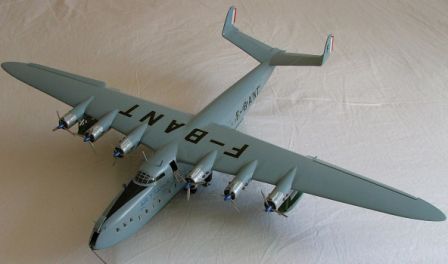
The
Late 631 was a high wing cantilever monoplane with a two step hull,
twin fins and rudders and retractable stabilising floats. It was all
metal with a wingspan of 57m (188ft) and full span ailerons and flaps.
The 142ft fuselage accommodated 46 passengers in several separate
cabins. There was a restaurant, bar, numerous direct exit (!)
lavatories and aft, a kitchen. All the passenger berths could be made
up as beds. The huge upper deck housed the flight deck, a navigation
room, engineers section and the radio room. In the bow was the mooring
compartment.
Building the Model
I
cheat. I use power tools whenever I can; it makes life so much easier.
I certainly could not do without my rotary tool because not only can I
drill out the windows, well holes in each corner and then much
patience with a knife, but with a sanding tool it makes short work of
shaping the huge parts.
Figure 1: It's Big!!
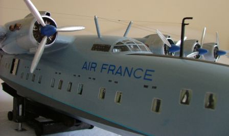
Figure 2: showing the window cut outs
Construction
- The
Fuselage
The
first job was cutting out and shaping the windows. It is not
difficult, just time-consuming. I drilled as many holes as I could in
each window aperture and then shaped them with a knife. Like the
Boeing Clipper the Late 631 has small upper berth windows. On the
Clipper I simulated them with black decal; on this one I drilled them
out! Its very fiddly! I then cut out the doors as I intend it to be
as detailed as possible. This of course meant building an interior. I
started off putting the kit provided bulkheads and floors in and then
began detailing.
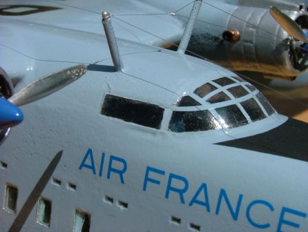
I
started with the flight deck. Two metal seats are provided as is the
dash-board. I scratchbuilt, from plastic card and sprue, the
instrument panels, navigators and engineers panels, the distinctive
autopilot column, the throttles and various other small details. Then,
from the spares box, came the steps and extra bulkhead, complete with
door, for the bow mooring compartment.
Figure 3: cockpit detail
Then
I tackled the aft main entry compartment. Plans show toilets opposite
the entry door so out came the plastic card again. Amidships there is
another door, presumably for crew use. This opens into a two berth
cabin so I needed to build the cabin. I then looked through the door
and realised I had to build the four berth cabin opposite and the
adjacent toilet compartment. So I did. Seats came from the scrap box,
wall from plastic card. At this point I realised that if I was not
careful I would have to build the whole interior. But if I curtained
the windows and sprayed the unseeable parts black I might get away
with it. So I did! Thats 96 curtains! When I built the Clipper I
glazed each window with clear plastic cut from a box top before
masking each one prior to spraying. I dont want to go down that
route again as I dont think it was very successful; instead I will
revert to my usual style of filling the window apertures with
clear-drying PVA. I am hoping that having the curtains, colourfully
painted, will help.
Repeated
checking of the fit of the two fuselage halves was continuous. Next
came the black spray can. I sprayed the whole of the interior black
before masking and spraying the centre cabin cream and the bow mooring
compartment and aft cabin silver. Then came the detailing. Although I
have excellent references and have used them to plan the general
layout the museum at Biscarosse has a mock-up of a 631 cabin, how they
used to travel in those days! I have also made considerable use of modeler's
licence on the grounds that it is better to see something
through the canopy and doorways than very little highly accurate
detail hidden by bulkheads and that only I know is there. The mooring
compartment gained ropes and fire extinguishers, painted red, and the
flight deck received dials, notices, knobs, seat belts and maps. I
then joined the fuselage halves by taping them together and running
thin superglue along the joint. A considerable amount of filler and
sanding later I have what is beginning to look like an airliner.
The
Tail
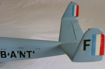
Figure 4: the tail parts
Now
this is where thing start to get complicated, but as in so much else
patience, ingenuity and common sense will ensure that it works out in
the end. I hope! The main complication is that the parts are not the
same size or shape and the panel lines are in different places. So
having scraped and sanded the edges to get the thinnest possible
trailing edge, I joined the various halves together. I put plastic
tabs at the end of the tail planes to aid the joining of the fins,
before scoring around the outlines of the elevators and rudders. They
were obviously not designed to be cut out as none of the lines meet
up! Perhaps I should have cut them out before joining the halves
together but that would have created more problems. As it is I am
going to fill the spaces with small strips of plastic card and then
shape them all to fit. It will be time consuming but should not be
difficult. I am dreading assembling the main wing! Ive done it! At
least I have filled in the gaps with plastic card and filler; I have
yet to start the sanding/shaping.
Intermission!
I
am now thinking about the main wing flaps. I think they are the
extending Fowler type flap and what I need is a kit like that
for the B-377/ B-50. As I dont think it is currently available and
probably wouldnt fit anyway I will have to think again. At the
moment it looks like cutting them out, making up the flap with card,
lining the wing with ribs and then hoping it all goes together.
I
never thought it would happen to me (well you dont do you?) but
while working on the fuselage cut out for the tail wings I managed to
glue my fingers to the plane with super-glue! While Doris Day and Rod
Taylor were gleefully cavorting around the telly as make-believe spies
I was busy trying to pry my fingers free using Locktite glue remover
and SAMs scale rule; (I knew it would come in handy one day!) all
of it much to the amusement of my wife. It had happened as I was
running some super thin glue inside the main fuselage join which
had come apart after I had cut away the area where the tail plane
sits. I had just completed the sanding and finishing of the tail plane
and fins and now need to fit them to the fuselage. They actually look
good; all that hard work has paid off.
It
is now some weeks later, my fingers have recovered and although I have
been doing some modeling I havent actually been doing any writing
up as I have been busy setting and marking exam papers. Having spent a
great deal of time on the internet trying to find new photos or
drawings of the large Late, with little success, I have realised that
lowering the main flaps is more likely to be educated guess-work
rather than known fact but I will go ahead anyway. The one photograph
I do have suggests that they extend a little and then droop, relying
on shape to increase lift, so this is what I will attempt. I have also
discovered that the outer nacelles that house the retracted floats
also form part of the flap, presumably the flaps could only extend
when the floats were lowered. This does complicate matters a little
but I am sure I shall manage.
Back
at the tail!
The
tail now looks very good. Having attached it to the fuselage and
lining it up by rack of eye I spent several hours with filler,
sandpaper and glue refining the final shape. The separated fins and
elevators fit in their respective slots but it did take a lot of work
getting them to an acceptable shape.
The
Engines
Six
engines! The two outer nacelles also house the floats, and, as I have
just worked out, also have to hinge with the flaps. Anyway I cut out
and sanded all the engine halves, initially using my mini-drill with
sanding disc followed by a sanding block. I had already decided not to
use the awful kit engines but rather white-metal replacements from
Aeroclub. So I cut out six discs of plastic card and slotted them in
level with the cooling fins before joining the nacelles together. I
did not join the rear of the outer nacelles together in the belief
that it would aid their later fitting. When all was dry I fitted a
rotary sander to the mini-drill and attacked the engine fronts.
Figure 5: The engine
fronts
They
needed a lot or rounding and I felt the cowlings were too narrow. Also
I could not get the engines in if I did not widen them! I then cut out
the float part of the outer nacelles and the doors. Then came
the inevitable final sanding, shaping and test fitting. With the wing
not yet built this latter part was just guesswork!
The
Main Wing
I
sanded the wings in the traditional way and then put them together.
Each wing half was a different shape so the putting together was
purely hopeful. I did try to line up the aileron lines though. The
trailing edges needed a lot of filler and then I shaped the wings.
They are very flimsy and there is no obvious means of attaching them
to the fuselage. Fortunately a rocket landed in garden a few months
ago (a firework in November!) and the stick makes an ideal spar.
Holding the wing against the fuselage I drew in their positions and
then cut holes for the spar. To get the correct dihedral I sawed ¾ of
the way through the stick before gluing and stapling it to the correct
angle. (I have no idea what the angle is, it just looks right!) Quick
setting epoxy secured it in place and will also hold the wings in
place. The wingspan of the real thing is only 7 ½ feet less than that
of a Boeing 747, and it was designed in 1938!
Now
the challenge...........
Figure 6: Overhead view of the
ailerons
In
the end it has not proved as scary as I had expected. I scored round
the flaps and ailerons with a scoring tool from Bare Metal in the USA
before using a knife to cut them out. The wings are now even weaker,
but fitting plastic card, suitably shaped, into the gaps has helped to
strengthen them. Card has also backed the flaps and ailerons. Its
actually looking quite good now, unlike our Rugby and football teams
who both received a hiding this weekend!
I
have now finished the wing, unfortunately without putting fingertips
to keyboard until now! This means that I have fitted the engines and
tested out the flap and aileron placement. I soon worked out, luckily
before gluing, that the four inner nacelles are not the same (they
look identical!) and must be fitted in the correct places. This done I
numbered them so when I did stick them they were right. All needed a
considerable amount of filler to blend them in. It was a case of fill,
sand, check, fill, sand and after a final check, coat with poly glue.
This has the effect of filling any minor blemishes and gives a smooth
surface ready for the final rub down. Once that was done it was a
matter of fitting the various intakes. I really did not feel like
fiddling with tiny vac-form parts so I raided the spares box and
a Sainsburys fruit drink carton. The former offered up some DC-3
intakes which fitted neatly to the tops of the engines and the latter
a plastic drinking straw which, when cut in half, made perfect lower
intakes.
|
|
Figure 7: the wings, flaps
and engines
While
all this was going on I also managed to sort the flaps and the floats.
The flaps were rounded with filler and then, to make them look more
realistic, and this is just guesswork as my references have few
decent pictures of the flaps, I fitted some fine screws to make
extending mechanisms. I now think they are hinged father than
extending so I will model them thus. The floats are pretty basic so I
enhanced them by cutting notches in the fronts to make the retraction
mechanism look more realistic. Again it was not difficult, just
finicky as it meant cutting and shaping the notches then lining them
with plastic card. I placed the card quite crudely then, when it
was dry and strong, cut it to shape. The floats needed a bit of extra
shaping, but even so they are not the same shape or size as each
other. I hope no one notices!
I
have now got to the stage of final
assembly! This will require plenty of 5-minute epoxy and layers of
filler. Well, here goes!
Final
Assembly
The
first job was to attach the wings. I had wooden spars in place so I
just covered the ends with quick drying epoxy and held on! True to
form the wings were not quite identical but with considerable help
from Mr Milliput and my mini drill sander they do at least look
vaguely level.
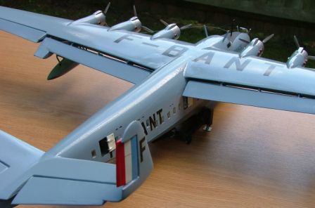
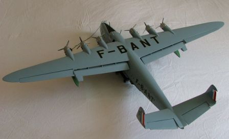
Figure 8: The wing span is huge!
Incidentally,
while rereading one of my references, Histoire et Maquettisme I
discovered that this French language periodical had in fact commissioned
this model from Contrail to accompany the article in the magazine. It
was spread over two issues but I only have the first, and it
came with the model! I wonder if Neil Gaunt [AIM own the Contrail
moulds] will re-release it?
The
model began to take shape and I couldnt help thinking of the brave
men who hid, and then rebuilt, the original. Filler around the wing
roots completed the blending in of the wings and fuselage; varying
grades of wetndry completed the job. Again it is not difficult;
it just requires patience, and fortunately she is in constant
attendance. Going the whole hog I then fabricated flap track
from lengths of tubing just to add that little bit of extra detail. It
is probably wrong but it looks better than plain plastic. I did the
same in the float nacelles: adding tracking for the supports and
retraction mechanism and nacelle door levers adds that little bit
extra. I am not a detail fanatic but on a model of this size bare
expanses of plastic are not realistic! Fitting the flaps was straight
forward (after trimming one to size, as I said each wing is slightly
different) and they certainly add something to the model.
Figure 9: the flaps
Fitting
the rudders (offset slightly), elevators (drooping slightly) and the
ailerons (one up, one down to match the rudder turn) was next. I used
superglue and was careful not to overdo the angles. Photos show that
under the wings there are what appear to be large aileron actuating
thingies but I cant see how they are supposed to work so I
have modeled them as lever actuator by adding fine fuse wire to make
the rods. I based this on the mechanism of the big planes
predecessor, the Late 521. Again it may not be right but it
looks good!
The
Late 521 is modeled by Aerovac of France in 1/72 and is an excellent
and straight forward vacform, but on that one too I offset all the
flying surfaces. It has made into a most impressive model.
I
next fitted the Aeroclub engines. For this I used quick setting epoxy
as I needed to make sure that the engines all appeared level and
straight otherwise the props would all be at different angles. Plenty
of epoxy spread on the back of each engine and then pushing the engine
gently into the nacelle and holding it for a little while with a prop
in place made sure they all look even. It was as straight forward as
it sounds!
I
am not a happy man. I should not have put the floats on before
painting, I should have air-brushed not sprayed, in short I am feeling
depressed because my magnificent model is going to need a lot more
work for it to be truly magnificent.
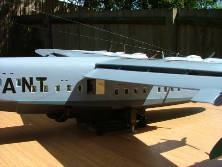
The
Floats
Figure 10: the float assembly
As
readers may have gathered from the preceding paragraph I fitted the
floats before painting. This means that I have to hand paint the
struts in situ, not an easy task. The floats themselves went on quite
well; I made up the front supports. I glued them in place and then
attached the rear strut at the same time as the float.
Then
came the aerials. Always the weakest part of any model I decided that
as they were so prominent on this model I would make them strong. They
are made of paper clips, with the larger aerial covered in plastic
tube. They will have nylon thread strung between them.
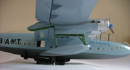
Painting
Even
by this stage I was still not quite sure which boat to do. All too
many aeroplanes of this era are either all silver [aluminium] or
camouflaged and I wanted something different. Rereading, yet again, my
references, but this time for colour scheme, I came across a picture
of F-BANT that was not aluminium. The text said it was painted,
probably blue. Further reading suggested that F-BANT was the second
631 built, in 1942, and was the one dismantled and hidden by the
Maquis. It was reassembled in 44 and 45 and made its first
trans-Atlantic flight in October 1945. The kit provided decals for
F-BANT
but gave its colour scheme as natural metal.
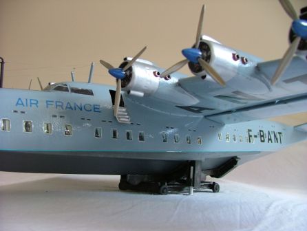
Figure 11: the only place to
spray was out in the garden!
I
opted for the blue version and car spray paint! After masking the
cockpit canopy and the window apertures I sprayed the plane with
Halfords Plastic Filler Primer. It took two cans! After doctoring
the revealed imperfections I rubbed it down with a scouring pad and
sprayed it with 2 cans of Ford Ceramic Blue. I rubbed that down with a
scouring pad, removed the masking and gave it two coats of Johnsons
floor polish. The decals were old and yellowed but with the help of Mr
Johnsons marvel the main lettering went on. I threw the rest out
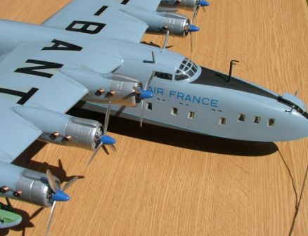
and used spares box replacements. Then the detail painting started.
Engines, rudders, window surrounds, curtains, canopy framing, float
recesses, antiglare panel, doors, and planning bottom all needed to be
done. Masking tape to give crisp lines is essential. A final coat of
Klear sealed it all.
The
picture below shows the front detail.
Finishing
Touches
Aerials
were made of invisible thread, i.e. smooth smoke coloured nylon
which gives scale thickness but is almost invisible. Door hinges
were fashioned from paper clips, door handles from fuse wire and the
doors hung. Aeroclub metal propellers were polished, blue spinners
were added [reshaped DC-6 units] and the props attached to the engine
fronts.
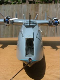
Finally
I made a beaching cradle, my own invention but based on one
lurking in the background of one of my photos, and, raiding my
wifes jewellery box, a mooring chain made from weathered Sterling
Sliver!
Figure
12:The Bow mooring compartment
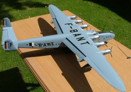
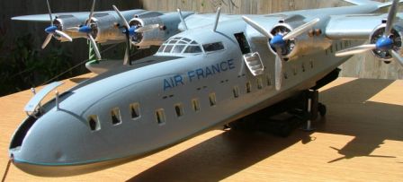
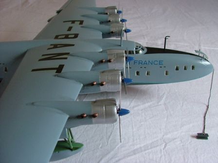
Figure
13: 6-engined
monster!
The
real F-BANT, named Lionel du Marmier, went through all sorts of trials
and tribulations, including shedding a propeller in mid Atlantic which
wrecked a few passengers, their cabin and an engine, forcing the pilot
to complete the crossing on only 4 engines: 3 on one side and 1 on the
other! Like me, it always seemed to be in trouble when young but was
never allowed to grow old gracefully, finally being scrapped in 1956,
some years before I was born. The model took me the better part of
eight months to build and there were times when I felt like scrapping
it too, but I am pleased with the final result. My next boat? The
1/72 Do X from Combat Models!
Door
and flap detail
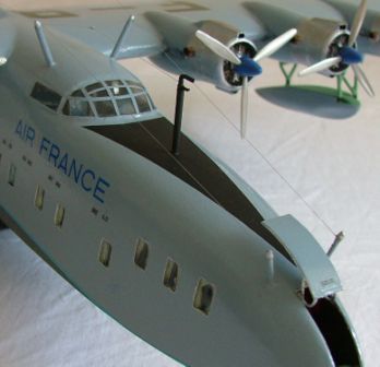
Figure
14:F-BANT
as she may have been in October 1945.
Bibliography
Aeroplane
Monthly, January 1993.
Histoire
et Maquettisme, September 1989.
[Le
Musee dHydravaition, Biscarosse, France.]
The
World Wide Web, but it does not have any more than is available from
the sources above.
|